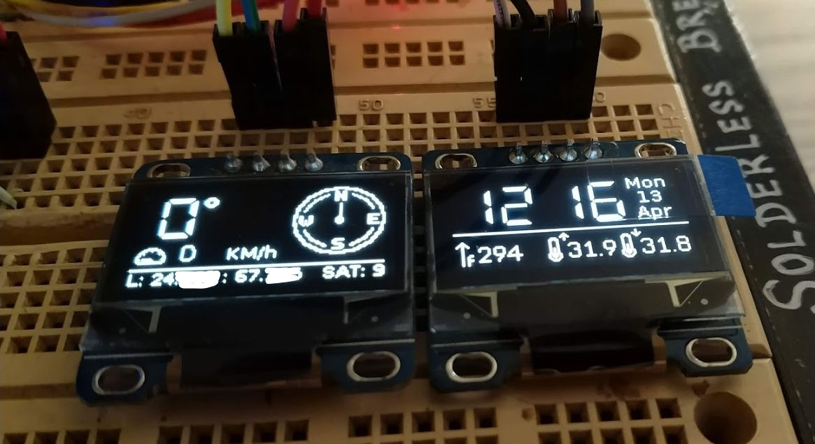
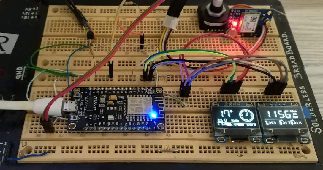
Often you need to draw a line at certain angle, and you find it hard to recall the math you learned in school to do this calculation. Same was the case with me recently when I was working on DashPanel-Arduino project.
First, I searched for ready to use snippet someone posted online, but I was out of luck. As the last resort, I looked up actual equation and converted it into a simple function which can be easily pasted in any Arduino source file.
#define DEG2RAD 0.0174532925

void drawAngularLine(int x, int y, int length, int rotation)
{
  float angleRadians = DEG2RAD * (rotation - 90);
  float x1 = x + cos(angleRadians) * length;
  float y1 = y + sin(angleRadians) * length;

  // SSD1306Wire I2C display object
  display1.drawLine(x, y, x1, y1);
}
While working on same project, I wanted to rotate a bitmap at runtime and draw on attached I2C OLED display. I stumbled upon this post on Arduino forum, and tweaked it a bit for my needs.
#define DEG2RAD 0.0174532925

void drawRotatedBitmap(SSD1306Wire *display,
                       int16_t x, int16_t y,
                       uint8_t w, uint8_t h,
                       const uint8_t *bitmap, uint16_t angle)
{
  int16_t newx, newy;
  uint8_t data = 0;

  float cosa = cos(angle * DEG2RAD), sina = sin(angle * DEG2RAD);

  x = x - ((w * cosa / 2) - (h * sina / 2));
  y = y - ((h * cosa / 2) + (w * sina / 2));

  for (int16_t j = 0; j < h; j++)
  {
    for (int16_t i = 0; i < w; i++)
    {
      if ((j * w + i) & 7)
        data <<= 1;
      else
        data = pgm_read_byte(bitmap++);

      newx = 0.5 + x + ((i * cosa) - (j * sina));
      newy = 0.5 + y + ((j * cosa) + (i * sina));

      if (data & 0x80)
      {
        display->setPixel(newx, newy);
        //display.drawPixel(newx, newy, 1);
      }
      //else
      //  display.drawPixel(newx, newy, 0);
    }
  }
}
There’s a trick with this one. You need to make the bitmap size in multiples of 8, like 16×16 icon, 48×48 etc. Once you make 1bit bitmap (.bmp) using Photoshop or MS Paint, you will need to convert it to byte array using Image2Bitmap utility to use in your Arduino code.
For example, an arrow icon converted to byte array would look like this:
const static uint8_t PROGMEM icon_nav_arrow_16x[] {
	0x00, 0x00, 0x00, 0x00, 0x01, 0x80, 0x01, 0x80, 0x03, 0xc0, 0x03, 0xc0, 0x07, 0xe0, 0x07, 0xe0,
	0x0f, 0xf0, 0x0f, 0xf0, 0x1f, 0xf8, 0x1f, 0xf8, 0x3e, 0x7c, 0x3c, 0x3c, 0x00, 0x00, 0x00, 0x00,
};
I hope these code snippets will help you save some time. Happy coding!


[…] Blog post: https://chall3ng3r.com/blog/2020/04/drawing-rotated-lines-bitmaps-with-arduino/ […]