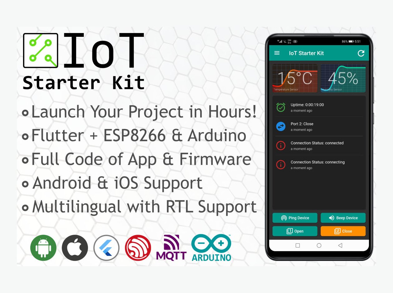
IoT Starter Kit for Makers

There are so many situations where you’d want to add automation to an electrical appliance, remotely control it or to keep check on it in real time.

You’d probably start by making an Arduino based hardware device with needed components / modules. Programming firmware to read values and take actions based on those values, or just publish the values online service to access them from anywhere. Last part will be to have some way to get it talking with your mobile phone.

Introducing our Flutter ESP8266 IoT Starter Kit, its two projects in one pack!

Flutter ESP8266 IoT Starter Kit – App in Dark Theme

For last few years, we’ve been doing projects which needed such automation, remote control or monitoring. We developed a template project, cloned it for every new requirement and customized as per our needs. It’s a boilerplate with all the basic requirements such as device settings, connectivity, data publishing and most importantly keeping device connected.

We decided to help other developers by releasing a ready-to-go package, full source code of a Flutter based mobile app along with ESP8266 firmware. Its available now at CodeCanyon, follow the link below:

https://codecanyon.net/item/flutter-esp8266-iot-starter-kit/29599018

Once you get copy of Flutter ESP8266 IoT Starter Kit, all you have do to is open both projects one by one in VS Code, and build. The steps are described in online documentation, which are quite easy to follow.

App Screenshots and Wiring Diagram

We just added pre-compiled APK on product website so you can try out the app as well, visit the following link for more:

https://orison.biz/projects/flutter-esp8266-iot-starter-kit/

If you have any questions, feel free to leave a comment below, I’ll try to get back to you as soon as I can.

P.S. Pre-compiled app connects and share data from live embedded device. We just replaced relay board and buzzer with LEDs so it doesn’t make noise :)

Drawing Rotated Lines and Bitmaps with Arduino

Often you need to draw a line at certain angle, and you find it hard to recall the math you learned in school to do this calculation. Same was the case with me recently when I was working on DashPanel-Arduino project.

First, I searched for ready to use snippet someone posted online, but I was out of luck. As the last resort, I looked up actual equation and converted it into a simple function which can be easily pasted in any Arduino source file.

#define DEG2RAD 0.0174532925

void drawAngularLine(int x, int y, int length, int rotation)
{
  float angleRadians = DEG2RAD * (rotation - 90);
  float x1 = x + cos(angleRadians) * length;
  float y1 = y + sin(angleRadians) * length;

  // SSD1306Wire I2C display object
  display1.drawLine(x, y, x1, y1);
}

While working on same project, I wanted to rotate a bitmap at runtime and draw on attached I2C OLED display. I stumbled upon this post on Arduino forum, and tweaked it a bit for my needs.

#define DEG2RAD 0.0174532925

void drawRotatedBitmap(SSD1306Wire *display, 
                       int16_t x, int16_t y, 
                       uint8_t w, uint8_t h, 
                       const uint8_t *bitmap, uint16_t angle)
{
  int16_t newx, newy;
  uint8_t data = 0;

  float cosa = cos(angle * DEG2RAD), sina = sin(angle * DEG2RAD);

  x = x - ((w * cosa / 2) - (h * sina / 2));
  y = y - ((h * cosa / 2) + (w * sina / 2));

  for (int16_t j = 0; j < h; j++)
  {
    for (int16_t i = 0; i < w; i++)
    {
      if ((j * w + i) & 7)
        data <<= 1;
      else
        data = pgm_read_byte(bitmap++);

      newx = 0.5 + x + ((i * cosa) - (j * sina));
      newy = 0.5 + y + ((j * cosa) + (i * sina));

      if (data & 0x80)
      {
        display->setPixel(newx, newy);
        //display.drawPixel(newx, newy, 1);
      }
      //else
      //  display.drawPixel(newx, newy, 0);
    }
  }
}

There’s a trick with this one. You need to make the bitmap size in multiples of 8, like 16×16 icon, 48×48 etc. Once you make 1bit bitmap (.bmp) using Photoshop or MS Paint, you will need to convert it to byte array using Image2Bitmap utility to use in your Arduino code.

For example, an arrow icon converted to byte array would look like this:

const static uint8_t PROGMEM icon_nav_arrow_16x[] {
	0x00, 0x00, 0x00, 0x00, 0x01, 0x80, 0x01, 0x80, 0x03, 0xc0, 0x03, 0xc0, 0x07, 0xe0, 0x07, 0xe0,
	0x0f, 0xf0, 0x0f, 0xf0, 0x1f, 0xf8, 0x1f, 0xf8, 0x3e, 0x7c, 0x3c, 0x3c, 0x00, 0x00, 0x00, 0x00,
};

I hope these code snippets will help you save some time. Happy coding!

Project DashPanel-Arduino

Starting a new open source project DashPanel-Arduino. The aim is to develop a low-cost, easy to make gadget to show usable info for trip. It uses Arduino framework on ESP8266 WiFi enabled microcontroller.

The list of components is quite short at the moment,

  • 1x ESP8266 ModeMCU compatible DevKit
  • 1x GPS module – blox NEO M6
  • 2x OLED 0.96″ displays – I2C interface
  • 2x DS1820 temperature sensors

The initial version features following data on two OLED displays:

  • Current course with compass view with numeric value
  • Current speed
  • Latitude and longitude
  • Number of satellites locked
  • Clock with date and weekday
  • Altitude
  • Cabin & ambient temperatures

Project Setup and Repo

DashPanel-Arduio is developed using VS Code editor with PlatformIO extension for ease of environment setup, programming and deployment.

Before you clone the repo, just install VS Code, add PlatformIO extension to it and you’re all ready to build.

Start VS Code, go into Source Control section and click Clone Repository, paste the link to DashPanel-Arduio repo: https://github.com/chall3ng3r/DashPanel-Arduino

Once clone process is completed, from VS Code’s command palette select “PlatformIO Build” option or use the shortcut keys Ctrl + Alt + B. The first build will take a bit of time as it will download required SDKs and libraries. Give it few minutes. If there are no errors, everything is okay and you are ready to upload build to dev board.

You can setup the components on breadboard like I’ve done, connect NodeMCU with USB of your PC and chose PlatformIO Upload option from command palette or use shortcut keys Ctrl + Alt + U.

NodeMCU GPIO Connections:

  • Software Serial for GPS module: 13, 15
  • I2C for OLED displays: 4, 5
  • OneWire DS1820 Sensors: 2

The project is still work-in-progress, and not yet in final form. The plan is to make a 3D printable enclosure.

Future Plans

The reason for using ESP8266 for this project is to enable WiFi AP on it and have a webserver to serve mobile and PC optimized settings page.

Some of ideas include:

  • Setting time zone offset. Currently hard-coded.
  • Set destination coordinates and then it will show how far and which direction is the destination.
  • Maybe different screen layouts to choose from. Like one for off road trip, another for city trip, etc.
  • Feature to record the GPS coordinates in standard GPX format, then upload to cloud service when reaching in range of saved WiFi after a trip.

Why I needed to make this project? Back story is shared on PakWheels forum.

Do share your ideas to improve it further or you can join on GitHub to contribute.

Font Converter for Arduino

Currently working on a DIY project for my SUV where I needed to use ESP8266 WiFi enabled microcontroller with two tiny I2C displays and a GPS. I found a great display library by Daniel who goes by the name Squix, known for sharing Weather Station and other awesome open source projects. If you’re into DIY embedded hardware, do check out his blog https://blog.squix.org/

Squix’s display library can use font generated by online Font Converter which have good list of fonts to select from. Sometimes a custom font is needed, like in my case, and I struggled to quickly get my own font converted to supported format.

Searched for and found some options, but was not happy with them. Thanks to DanielĀ  for sharing source code of Font Converter, I digged the source and extracted just the part to convert the font.

I did bit of modification to pass font name, size and regular or bold option arguments to the console utility. I created a GitHub repo where source and compiled binary is available.

Usage example:

> java FontConverterV3 "Tahoma" 14 r > font-tahoma.h

Download and repo:

Soon enough, I will share the project which needed this utility.